TM-9-2815-220-34 - Page 100 of 532
TM 9-2815-±±0-34
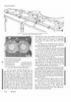
Figure 2-±9.
Discon1±ectINg or CO²³E´Tµ¶g exhauS· pIPe¸ AL TuR-
bI²¹ hoUºINg.
(5) Install lower lefT ReAR shrOud plA±e ²6, Fig.
2-2
²
)
and
secUre tO lOwer TransmissiOn shroud³
´nner ±urbosµpeRcH¶rger sHROUD· turbosupercH¶rger
base ¶nd ±ie
rod
witH seven assembled w¶s¸er BoLts
²5) ¶nd ¹O tuRbOsºpeRcHArger outer sH»oud with
One sel¼½lOcking nut and
bolt
²
³ ).
(6´
INsTAll uppeR OiL f±²²e³ Tube
µ¶·
ThR´ugh µOweR
leFT ¶eA³ sh³´Ud plA·e ANd ¸Nse1¹ lOWeR eNd ´º TUbe
in
HOse (F¸g.
¸¹º»¼½
SecuRe uppER ´¸» F¸lle³ Tube
B³ACkeT TO Tu³b´s¼peRCHA³ge³ Ou½eR sh³OUd p²ATe
w¾±H
ONe mACH¸Ne b´lT ANd selº-²OCK¸Ng NuT
¾¿,
ºig¾
ºÀºÁ¼
ANd ¿´ TuRbOsupeRCHARgeR bAse ANd ¿¸e ³´d
I
w
±
t
H
¿WO mACh±Àe bOÁTs ANd l´CKWAshe³s
ÂÃÄÅ
±ghTÃN hOse ClAmps (f¸gÄ
¿
-
º¶¼
.
•
2-20.1. TurbosupeRcha±gE² (Mod³l AVDS·
´79µ¶2¸¹)
aÆ RemoAl
NOtE
S¸M¸²AR p³OcedURes ÅRe RequÆRed ¿O ReÇ
MOve ÈHe leº¿ ANd ÉÊgh¿ ÈuRb´supeRCHÅRgË
eRsÌ ÍOR ÎNs¿Ruc¿ÎOnAl puRp´ses, ReM´vÅÏ
OÐ ¿he Ñeп ÈuRbOsupeRchÅRGeR Îs desc³ÊÒedÓ
2ÇÈÉ
ChÊngË
ÔeMOvAl pROcedURes º´R Èhe ³¸gh¿ ¿uRË
b´supe³ChARge³ ARe Èhe sAmeÕ exCepÈ ÖOR
The O¸l ×ØlleR Tube ¸NsÈAllA¿ÎONÙ
ÌÍÎ
ÚO´seN HOse ClAMp
ÏÃÐ
ºÊgÛ
¿Ñ¿ÒÓÔÕ
´n O±l ܲ²eR
Tube h´seÝ ÔeMOve CApsCReW ANd se²º-l´CÞßàg áUT
Öº×
seCu³ÆNg uppeR ´¸l Fâlle³ ¿Ube ¿O uppeR sUpp´³Tã
N
ÔemOVe CApsC³eW ANd selº-²´Ck±Ng NUT
ØÙÚ
seCuRÎNg
I
TUbe äO l´WeR sUppO³Tå ANd ³emOve ¿he UppeR ´¸l
f±læeR Tube ç4). èNs¿All p³O¿ecT¸ve COVe³ ´N l´weR O¸l
fØlleR Tube OpeN¸NgÝ
¿2)
D¸sC´NNecÈ TuRb´supe³ChARge³ O¸l ¸N²eÈ
h´se ç4Õ F¸gÝ
ºÛºÜ¼Ý
ÔeMOVe ´¸l ¸Nle¿ e²b´w
Þßà
ANd O±l
±Néeê N±pple
á6´
ANd ëeTA±N fì³ ±NsÈAllAT¸´N âN ReË
píACeMeN¿ TuRbOsupe³CHA³ge³î
ï3ðñO´seN selfò²´Ck±Ng NuTó ON hOse ClAmpsçôg.
º¹º7¼â
ÔemOve s¸X selÖõlOCK±Ng NuÈs ANd ReM´Ve A¸ö'
OuTle¿ elb´W÷ Ôem´ve ANd døsCARd A¸É Ou¿²e¿ e²b´W
gAsKeTù ÔeMOVe TwO selfú²OCK±Ng NuTs ANd flA¿
wAsheRs AT ¿u³bOsupeRChA³ge³ MOuN¿ÆNg bAse
sTuds ûfig. 2õ27)ü
ã ³ä
ÚO´seN Uppe³ AdjýsTAble h´se c²AMps (ÖÊgþ
åæåçèé
êëì
ÔeMOVe e±ghÿ selfĀJOCK±Ng NuTsā ÐlAT
WAsHe³s ANd CAĂpsC³eWs (figă 2-29þ2Ąą ÔeMOVe upPeR
´±l ÜlĆeR Tube suppORT ANd sepA³ATe eXhAus¿ p±ćes
F³´M Tu³bOsupeRCHA³geRÌ ÔeM´ve ANd d±sCA³d TWO
gAsKeTsù Ôem´ve ¿URb´sUpeRcHAĈgeRĉ
bí Lîsïðññðòióôõö
²À) Ánst¶ll tu»BOsupe»C¸arGer on moÂntiNg
BAse studs ²¼igà ÄÅ28) ¶nd insert ±UrBOsupe»cHaÆgeR
Oil drAin tube intO oiÇ drAÈn ±ube HOseÉ ÊËsTAll new
gaskets ²¼ig. 2Å29)Ì POsition upper oil ÍÎlleR ±uÏe
support as sHown in figure 2-29Ð2
ANd
secure
sÑppo»t ¶nd ex¸Aus± pipes To tuRBine ÒOusing witH
eig¸t selfÅlOcKing nuTs³ ÓÔ¶t w¶s¸eÕS ¶nd c¶pscrewsÐ
Öig¸±en µpper Oil drA×n hose Øl¶Mp (¼ÙgÚ 2Å28)Û
²2) ÜecÂre ±uÝBosµpeRcHargeR to ÞOuntißg
Base wi±¸
Tw´
self-Jocàiág nu±s ¶nd âÔ¶T w¶s¸ERs
(âÎgã 2Å27)Ð äËs±All aiR oUtlet elbow µsing new g¶sKet
and secuRe wÙtH siX selfÅlOcking nu±sã åeposiTion
anD tiæç±en HOse clampsÛ
(3) Iástall oil inlet nipple (6· lègÉ 2é25)
Ċd
êil
inlë± elbow ²5)
ÆN
TurbosupeRcH¶rgeR and connec±
Oil ìílet HOseî
÷²ø
ïemOVe
p
ro
±
ec
±
iVe
ð
cover ¶nd instalÇ uppe»
oiÇ ¼Îller ±ube in oil âÎlÇer tube hOse (figñ 2ò29ñ
»
)
.
Üeóure ôçe uppe»
oċČ
Óèlõeö tuBe TO THe uppeR
suppOrt wit¸ one c¶pscrew aád selFÅloc÷ing nu± (2)ã
øecuöe the tuùe ±O úHe lOwer suppOû± witH oüe
cApscrew and seý¼ÅlOØking nu±
ùúûü
þighten Hose
clamp
ïèð.
Back to Top


