TM-9-2815-224-34-P - Page 221 of 554
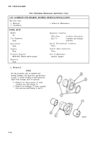
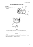
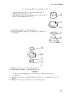
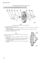
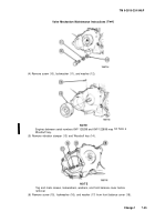
7-12. FRONT BALANCE COVER AND VIBRATION DAMPER REMOVAL/INSTALLATION.
(9)
TM 9-2815-224-34&P
Valve Mechanism Maintenance Instructions (Cont)
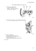
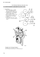
Mount dial indicator on end plate (5)
and check backlash between gears (2,
3, and 4). Minimum backlash is
0.002 in. (0.05 mm). Maximum
backlash is 0.008 in. (0.20 mm).
f. Follow-on Maintenance.
(1) Install flywheel housing (para 5-3).
(2)
Remove engine from engine stand (TM 9-2320-279-34).
END OF TASK
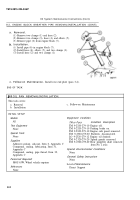
This task covers:
a. Removal
b. Installation
c. Follow-on Maintenance
INITIAL SETUP
Models
References
All
None
Test Equipment
Equipment Condition
None
TM or Para
Condition Description
Special Tools
TM 9-2320-279-20 Fan clutch removed.
None
Para 17-2
Water pump removed.
Supplies
Special Environmental Condition
Grease, automotive and artillery, Item 36,
None
Appendix C
Tags, identification, Item 61, Appendix C
General Safety Instructions
None
Personnel Required
MOS 63W, Wheel vehicle repairer
Level of Maintenance
Direct Support
7-43
Back to Top

