TM-9-2815-225-34-P - Page 120 of 736
TM 9-2815-225-34&P
0008 00
0008 00-30
BIG CAM III ENGINE REMOVAL (Contd)
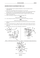
91. Disconnect ether quick-start tube (3) from atomizer (4) on intake manifold (1).
92. Position and secure suitable transmission jack under transmission (11). Ensure transmission
weight is supported by transmission jack.
93. Remove flywheel bolt access cover screw (5) from P-clamp (6) and flywheel housing (13) and
position P-clamp (6) away from flywheel housing (13).
94. Remove flywheel bolt access cover screws (5) and flywheel bolt access cover (7) from flywheel
housing (13).
NOTE
Rotate engine using accessory drive pulley nut to gain access to
flywheel bolts.
95. Remove twelve flywheel bolts (8) and washers (9) from flywheel (10) and torque converter (12).
96. Remove twelve transmission bolts (25) from transmission (11) and flywheel housing (13).
97. Attach tilt sling and lifting device to engine lifting brackets (2).
98. Remove two front engine crossmember mount nuts (23), four washers (19), two insulators (20),
and bolts (22) from front engine crossmember mount (21).
99. Remove four mounting bracket nuts (26), insulators (28), eight washers (27), and four bolts (15)
from mounting brackets (16).
WARNING
Use extreme care when handling heavy parts. Provide adequate
support and use assistance during procedure. Ensure that any
lifting device used is in good operating condition and of suitable
load capacity. Keep clear of heavy components supported only
by lifting device. Failure to do so may result in death or injury
to personnel.
Use pry bars to free engine hangups or snags. Do not use
hands. Failure to do so may result in damage to equipment or
death or injury to personnel.
100. Using lifting device and lifting sling, remove engine (17) from frame (14). Ensure there is proper
clearance between frame (14), alternator (24), engine (17), and power steering pump (18).
101. To mount engine on maintenance stand refer to WP 0009 00.
Figure 46. Ether Quick Start Tube.
3
4
2
1
TILT
SLING
Back to Top


