MWO-5-2350-262-35-4 - Page 152 of 207
MWO 5--2350--262--35--4
5--17
SECTION V ROUTING AND ELECTRICAL CONNECTION OF UPPER
CABLE ASSEMBLY W2
CAUTION
It is important that all W2 cable assembly branches and individual electrical connectors
be routed and dressed close to primary manifold behind hydraulic tubes and close to rear
wall of bowl to protect cable from possible damage.
NOTE
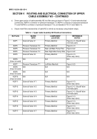
Steps a through h apply to Figure 5--12. Reference should also be made to FO 5--5.
a.
Route two branches of cable upper assembly W2 (2) to proper portions of bowl area. Upper area
electrical cable connectors P3, P4, and P30 branch out from one leg of W2 and mate with electrical
connectors in the main pump hydraulic filter area and near the suspension valve. All other W2 cable
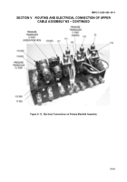
connectors branch from other leg of W2 and mate with electrical connectors on HDC primary manifold,
except for connector W2P7 that mates with pressure transducer T7 on left main manifold, at bottom of
bowl area. Note that lower cable assembly W3 (1) runs parallel to upper cable assembly W2 (2) down
left side of ejector bowl.
b.
Secure upper portion of cable assembly W2 to vehicle as necessary using tiedown straps, MS3367--1--9,
and existing cable clamps as required.
c.
Carefully route branch of upper cable assembly W2 (with connectors P3, P4, and P30) to main pump left
and right high--pressure hydraulic filter area and suspension valve as shown in Figure 5--12.
Figure 5--12. Upper Cable Assembly W2 Routing
Back to Top


