MWO-5-2350-262-35-4 - Page 153 of 207
MWO 5--2350--262--35--4
5--18
SECTION V ROUTING AND ELECTRICAL CONNECTION OF UPPER
CABLE ASSEMBLY W2 -- CONTINUED
d.
Dress upper portion of cable assembly W2 into filter area as shown in Figure 5--12 and make electrical
connections: W2P3 to connector on pressure transducer T3, W2P4 to connector on pressure transducer
T4, and W2P30 to connector on pressure transducer T12, as indicated in FO 5--5 and Table 5--3.
e.
Secure main filter area branches of cable W2 to vehicle as necessary using tiedown straps.
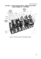
Table 5--1. Upper Cable Assembly W2 Electrical Connections
W2 PLUG
MATES
WITH
COMPONENT
LOCATION
REFERENCE/
NOTES
W2P1
Solenoid Valve V1
Primary Manifold
Figure 5--13, Shutoff Valve
(normally open)
W2P2
Pressure Transducer T2
Primary Manifold
Figure 5--13
W2P3
Pressure Transducer T3
Near Left Main Pump Filter
Figure 3--42
W2P4
Pressure Transducer T4
Near Right Main Pump Filter
Figure 3--42
W2P5
Solenoid Valve V5
Primary Manifold
Figure 5--13,
(three--way valve)
W2P6
(Does not exist)
N/A
N/A
N/A
W2P7
Pressure Transducer T7
Left Main Manifold
Figure 3--23
W2P8
(Does not exist)
N/A
N/A
N/A
W2P9
(Does not exist)
N/A
N/A
N/A
W2P10
(Does not exist)
N/A
N/A
N/A
W2P11
Solenoid Valve V11
Primary Manifold
Figure 5--13,
(three--way valve)
W2P12
Solenoid Valve V12
Primary Manifold
Figure 5--13, Shutoff Valve
(normally open)
W2P13
Solenoid Valve V13
Primary Manifold
Figure 5--13, Shutoff Valve
(normally open)
W2P14
Solenoid Valve V14
Primary Manifold
Figure 5--13,
(three--way valve)
W2P15
Solenoid Valve V15
Primary Manifold
Figure 5--13,
(three--way valve)
W2P16
Solenoid Valve V16
Primary Manifold
Figure 5--13,
(three--way valve)
W2P17
Solenoid Valve V17
Primary Manifold
Figure 5--13,
(three--way valve)
Back to Top


