TB-9-2320-280-35-15 - Page 112 of 168
5-88
TB 9-2320-280-35-15
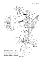
Figure 5-104.
Section XXXVII. SINCGARS CABLES INSTALLATION
NOTE
• This procedure applies to vehicles without existing antennas. For
vehicles with existing antennas, remove all control cables. (Refer
to TM 9-2320-280-20.)
• Previously routed cables have been removed from figure 5-104 for
clarity.
37-1.
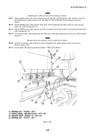
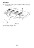
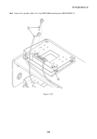
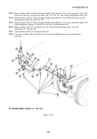
Route antenna cable (15) from left side of mounting base (19), down through center access hole (12),
under integrated rack (13), and under right-side tunnel insulation (16) towards rear of vehicle.
37-2.
Route antenna cable (17) from mounting base (19) to MT-6353/VRC mounting base (18).
37-3.
Route power amp cable (10) from MT-6353/VRC mounting base (18), up through center access
hole (12), and connect power amp cable (10) to connector on W1J1 cable (9).
37-4.
Route control cable (11) from MT-6353/VRC mounting base (18), up through center access hole (12),
to mounting base (19).
37-5.
Route antenna cable (14) from front of MT-6353/VRC mounting base (18) and under
integrated rack (13).
37-6.
Route two loudspeaker cables (2L) and (2R) from mounting base (19) up along windshield center
post (20) and secure with three loop clamps (4), two existing self-tapping screws (8), and existing
screw (21).
37-7.
Route left side loudspeaker cable (2L) along windshield frame (7) and secure with two loop clamps (3)
and existing screws (22). Connect speaker cable (2L) to left speaker (1).
37-8.
Route right side loudspeaker cable (2R) around right speaker (5) and secure to windshield frame (7)
with loop clamp (3) and existing screw (6). Connect right speaker cable (2R) to right speaker (5).
2L. LOUDSPEAKER CABLE – A3014038-3 – QTY. 1
2R. LOUDSPEAKER CABLE – A3014038-3 – QTY. 1
3. LOOP CLAMP – MS21333-102 – QTY. 3
4. LOOP CLAMP – MS21333-104 – QTY. 3
14. ANTENNA CABLE – A3014031-17 – QTY. 1
15. ANTENNA CABLE – A3014031-8 – QTY. 1
17. ANTENNA CABLE – A3014032-3 – QTY. 1
1
2L
3
22
21
20
2L
2R
4
2R
5
6
3
7
4
9
10
11
8
12
~
13
14
15
~
16
10
11
17
15
18
14
~
19
Back to Top


