TB-9-2320-280-35-15 - Page 107 of 168
5-83
TB 9-2320-280-35-15
NOTE
DAGR power cable positive lead insulation is ribbed.
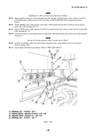
35-12.
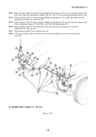
Attach shrink tubing (18) and terminal lugs (16) and (22) to PLGR power cable negative lead (21)
and DAGR power cable positive lead (19). (Refer to TM 9-2320-280-20 for terminal connector
repair.)
35-13.
Attach DAGR power cable positive lead (19) to 24V terminal board (24) located on cab enclosure
panel (25) with existing nut (17).
35-14.
Attach DAGR power cable negative lead (21) to ground strap (23) located on cab enclosure panel (25)
with existing nut (17).
35-15.
Coil excess positive and negative power leads, place beneath ground strap, and secure with tiedown
strap (20).
NOTE
Ensure all excess antenna cable is inside cab of vehicle.
35-16.
Coil excess antenna cable and store under integrated rack using tiedown strap as necessary.
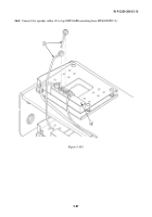
(Refer to figure 5-94.)
35-17.
Install right-side tunnel insulation. (Refer to TM 9-2320-280-20.)
Figure 5-99.
16. TERMINAL LUG – 7728780 – QTY. 1
18. SHRINK TUBING – MS23053/4-302-0 – QTY. A/R
20. TIEDOWN STRAP – MS3367-1-0 – QTY. A/R
22. TERMINAL LUG – 7728777 – QTY. 1
25
16
17
20
17
21
18
22
23
24
18
19
~
Back to Top

