TB-9-3950-253-13-P
PALLETIZED LOAD SYSTEM TRUCK, M1075 and M1075A1 (PLS) AND HEAVY EXPANDED MOBILITY TACTICAL TRUCK, M1120, M1120A2, AND M1120A4 (HEMTT), ENHANCED CONTAINER HANDLING UNIT (E-CHU)
TECHNICAL BULLETIN; OPERATOR AND FIELD MAINTENANCE, INSTALLATION INSTRUCTIONS, AND REPAIR PARTS AND SPECIAL TOOLS LIST
JULY 2009
TB-9-3950-253-13-P - Page 45 of 704
0006-5/(6 Blank)
0006
TB 9-3950-253-13&P
CONVERT SLIDER BEDS FROM CONTAINER TO FLATRACK CONFIGURATION – CONTINUED
Rear Twistlock Configuration
0006
WARNING
During this procedure, the twistlock assembly will be allowed to swing free unless it is
manually supported. Ensure no personnel are standing in the path of the twistlock
assembly. Failure to follow this warning may result in injury to personnel.
NOTE
•
Rear twistlocks require adjustment on HEMTT only.
•
Perform steps 1 through 7 for both right and left sides.
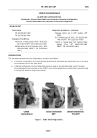
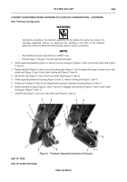
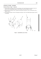
1. While supporting twistlock (Figure 5, Item 6) remove locking pin (Figure 5, Item 4) from rear slider bed (Figure
5, Item 3).
2. Rotate twistlock (Figure 5, Item 6) up until locking tube (Figure 5, Item 5) aligns with upper locking hole in rear
slider bed (Figure 5, Item 3) and insert locking pin (Figure 5, Item 4).
3. Remove R clip (Figure 5, Item 2) from rear slider bed (Figure 5, Item 3).
4. While supporting twistlock housing (Figure 5, Item 7), remove locking pin (Figure 5, Item 1).
5. Rotate anvil (Figure 5, Item 8) until aligned with opening in twistlock housing (Figure 5, Item 7).
6. Rotate twistlock housing (Figure 5, Item 7) up until it engages with twistlock (Figure 5, Item 6) and install
locking pin (Figure 5, Item 1)
7. Install R clip (Figure 5, Item 2) in rear slider bed (Figure 5, Item 3).
Figure 5.
Twistlock Assembly (Container to Flatrack).
06
END OF TASK
END OF WORK PACKAGE
5
1
6
7
8
7
3
2
1
5
4
3
2
4
6
Back to Top


