TB-9-3950-253-13-P
PALLETIZED LOAD SYSTEM TRUCK, M1075 and M1075A1 (PLS) AND HEAVY EXPANDED MOBILITY TACTICAL TRUCK, M1120, M1120A2, AND M1120A4 (HEMTT), ENHANCED CONTAINER HANDLING UNIT (E-CHU)
TECHNICAL BULLETIN; OPERATOR AND FIELD MAINTENANCE, INSTALLATION INSTRUCTIONS, AND REPAIR PARTS AND SPECIAL TOOLS LIST
JULY 2009
TB-9-3950-253-13-P - Page 54 of 704
TB 9-3950-253-13&P
Change 1
0007-8
0007
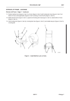
RETRIEVE LIFT FRAME – CONTINUED
Release Locking Pins
0007
NOTE
•
Perform steps 1 through 4 for both sides of lift frame.
•
Press UP and DOWN button on control panel as required to enable release of locking pin.
Keep up and down movement to a minimum.
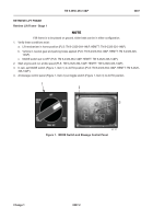
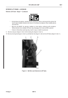
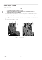
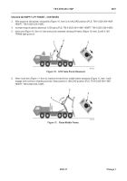
1. From left side of lift frame (Figure 7, Item 1), release lower locking pin anti-loose fastener (Figure 7, Item 3).
2. Pull out lower locking pin (Figure 7, Item 4) from securing tube (Figure 7, Item 5) and rotate locking pin to verti-
cal position.
3. Align locking pin (Figure 7, Item 4) with cradle (Figure 7, Item 2) on lift frame (Figure 7, Item 1) and push lock-
ing pin toward lift frame.
4. Lock anti-loose fastener (Figure 7, Item 3).
Figure 7.
Secure Locking Pin.
07
467-171
1
2
3
4
4
3
5
Back to Top

