TB-9-3950-253-13-P
PALLETIZED LOAD SYSTEM TRUCK, M1075 and M1075A1 (PLS) AND HEAVY EXPANDED MOBILITY TACTICAL TRUCK, M1120, M1120A2, AND M1120A4 (HEMTT), ENHANCED CONTAINER HANDLING UNIT (E-CHU)
TECHNICAL BULLETIN; OPERATOR AND FIELD MAINTENANCE, INSTALLATION INSTRUCTIONS, AND REPAIR PARTS AND SPECIAL TOOLS LIST
JULY 2009
TB-9-3950-253-13-P - Page 60 of 704
TB 9-3950-253-13&P
Change 1
0007-14
0007
PLACE LIFT FRAME ON GROUND – CONTINUED
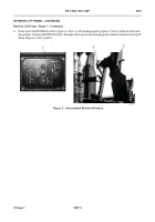
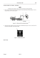
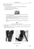
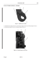
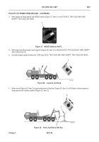
4. With engine at idling speed, set MODE switch (Figure 15, Item 1) to AUTO (PLS: TM 9-2320-364-14&P,
HEMTT: TM 9-2320-326-14&P).
Figure 15.
MODE Switch at AUTO.
07
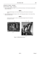
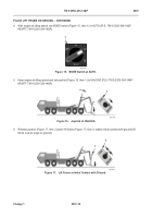
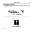
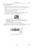
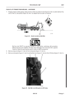
5. Keep engine at idling speed and set joystick (Figure 16, Item 1) to UNLOAD (PLS: TM 9-2320-364-14&P,
HEMTT: TM 9-2320-326-14&P).
Figure 16.
Joystick at UNLOAD.
07
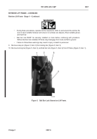
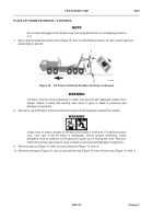
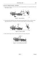
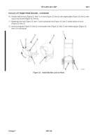
6. Release joystick (Figure 17, Item 2) when lift frame (Figure 17, Item 1) makes initial contact with ground (lift
frame is at an angle to ground).
Figure 17.
Lift Frame at Initial Contact with Ground.
07
467-045
1
467-078
1
467-079
1
2
Back to Top

