TB-9-3950-253-13-P
PALLETIZED LOAD SYSTEM TRUCK, M1075 and M1075A1 (PLS) AND HEAVY EXPANDED MOBILITY TACTICAL TRUCK, M1120, M1120A2, AND M1120A4 (HEMTT), ENHANCED CONTAINER HANDLING UNIT (E-CHU)
TECHNICAL BULLETIN; OPERATOR AND FIELD MAINTENANCE, INSTALLATION INSTRUCTIONS, AND REPAIR PARTS AND SPECIAL TOOLS LIST
JULY 2009
TB-9-3950-253-13-P - Page 59 of 704
0007-13
Change 1
TB 9-3950-253-13&P
0007
PLACE LIFT FRAME ON GROUND
0007
1. Verify these conditions exist:
a. Lift mechanism deployed (PLS: TM 9-2320-364-14&P, HEMTT: TM 9-2320-326-14&P).
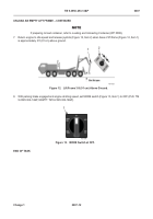
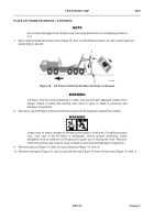
b. Lift frame on hook (
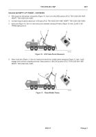
Unload Empty Lift Frame
).
c.
Stowage toggle switch set to OFF position (WP 0004).
d. NO TRANS light off (WP 0004).
WARNING
•
These instructions require adjustments to the lift frame. Beware that the frame may swing
on hook, especially in high winds.
•
During these adjustments, personnel must work outside the vehicle where there are
several projecting parts, and personnel are required to bend down. Take care when
bending and straightening. A hard hat is required.
•
Lift frame must be firmly positioned on solid, level ground with adequate support from
stands.
•
Failure to follow these warnings may result in injury or death to personnel and damage to
equipment.
NOTE
Perform steps 2 and 3 for right and left stands.
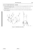
2.
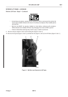
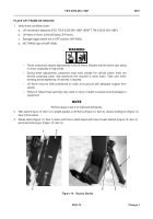
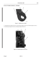
With stand (Figure 14, Item 1) in upright position on lift frame (Figure 14, Item 2), remove locking pin (Figure 14,
Item 3) from stand.
3. Rotate stand (Figure 14, Item 1) down until hole in stand aligns with hole in lower bracket (Figure 14, Item 4)
and insert locking pin (Figure 14, Item 3).
Figure 14.
Deploy Stands.
07
467-173
1
3
4
3
2
1
Back to Top

