TB-9-3950-253-13-P
PALLETIZED LOAD SYSTEM TRUCK, M1075 and M1075A1 (PLS) AND HEAVY EXPANDED MOBILITY TACTICAL TRUCK, M1120, M1120A2, AND M1120A4 (HEMTT), ENHANCED CONTAINER HANDLING UNIT (E-CHU)
TECHNICAL BULLETIN; OPERATOR AND FIELD MAINTENANCE, INSTALLATION INSTRUCTIONS, AND REPAIR PARTS AND SPECIAL TOOLS LIST
JULY 2009
TB-9-3950-253-13-P - Page 494 of 704
TB 9-3950-253-13&P
Change 1
0051-8
0051
HEMTT REMOVAL – CONTINUED
Reposition Hydraulic Control Box – Continued
00051
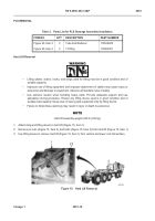
8. Remove two quick disconnect coupler fittings (Figure 7, Item 7) from elbow fittings (Figure 7, Item 2).
9. Remove two jam nuts (Figure 7, Item 8) and elbow fittings (Figure 7, Item 2) from bracket (Figure 7, Item 1).
Discard elbow fittings and jam nuts.
NOTE
•
Perform steps 10 through 18 for HEMTT M1120.
•
Perform steps 15 through 19 for HEMTT M1120A4.
•
Install longer end of fitting through bracket.
•
Hand tighten all fittings on installation.
10. Install two T-fittings (Figure 7, Item 3) and jam nuts (Figure 7, Item 6) on bracket (Figure 7, Item 1).
11. Install two quick disconnect coupler fittings (Figure 7, Item 7) on T-fittings (Figure 7, Item 3).
12. Install two tube end reducers (Figure 7, Item 4) on T-fittings (Figure 7, Item 3).
13. Install two hoses (Figure 7, Item 5) on T-fittings (Figure 7, Item 3).
14. Install two hoses (Figure 7, Item 5) on control box (Figure 7, Item 8).
Figure 7.
HEMTT Fittings Installation.
051
467-102
3
6
5
3
4
7
7
8
1
2
8
Back to Top


