TB-9-3950-253-13-P
PALLETIZED LOAD SYSTEM TRUCK, M1075 and M1075A1 (PLS) AND HEAVY EXPANDED MOBILITY TACTICAL TRUCK, M1120, M1120A2, AND M1120A4 (HEMTT), ENHANCED CONTAINER HANDLING UNIT (E-CHU)
TECHNICAL BULLETIN; OPERATOR AND FIELD MAINTENANCE, INSTALLATION INSTRUCTIONS, AND REPAIR PARTS AND SPECIAL TOOLS LIST
JULY 2009
TB-9-3950-253-13-P - Page 495 of 704
0051-9
Change 1
TB 9-3950-253-13&P
0051
HEMTT REMOVAL – CONTINUED
Reposition Hydraulic Control Box – Continued
00051
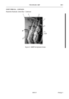
15. Loosen four nuts (Figure 8, Item 4) on lower angle fittings (Figure 8, Item 1) and move angle fittings
clockwise 45°.
16. If required, remove pressure test port (Figure 8, Item 5) and O-ring (Figure 8, Item 6) from hydraulic control box
(Figure 8, Item 7). Discard O-ring.
17. Tighten four nuts (Figure 8, Item 4).
18. If removed, install new O-ring (Figure 8, Item 6) and pressure test port (Figure 8, Item 5) on hydraulic control
box (Figure 8, Item 7).
19. Loosen four nuts (Figure 8, Item 3) on upper angle fittings (Figure 8, Item 2) and move angle fittings counter-
clockwise 30°. Tighten four nuts.
Figure 8.
HEMTT Reposition Angle Fittings.
051
Back to Top


