TB-9-3950-253-13-P
PALLETIZED LOAD SYSTEM TRUCK, M1075 and M1075A1 (PLS) AND HEAVY EXPANDED MOBILITY TACTICAL TRUCK, M1120, M1120A2, AND M1120A4 (HEMTT), ENHANCED CONTAINER HANDLING UNIT (E-CHU)
TECHNICAL BULLETIN; OPERATOR AND FIELD MAINTENANCE, INSTALLATION INSTRUCTIONS, AND REPAIR PARTS AND SPECIAL TOOLS LIST
JULY 2009
TB-9-3950-253-13-P - Page 496 of 704
TB 9-3950-253-13&P
Change 1
0051-10
0051
HEMTT REMOVAL – CONTINUED
Reposition Hydraulic Control Box – Continued
00051
WARNING
•
Appropriate safety precautions (including, but not limited to, wearing proper breathing
apparatus, hearing protection, safety goggles, etc.) must be observed when working with
CARC material.
•
All cutting and grinding must be done using an abrasive device only. Use of a cutting torch,
plasma cutter, etc., is not permitted.
•
Always wear gloves and a face shield or breathing apparatus when grinding painted
surfaces. Airborne particles may cause lung irritation or damage to eyes.
•
Failure to follow these warnings may cause injury or death to personnel.
NOTE
•
Perform steps 20 through 26 for HEMTT M1120 A4, then continue with step 27.
•
Proceed to step 27 for HEMTT M1120.
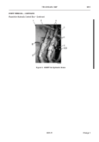
20. Cut bracket (Figure 9, Item 10) from hydraulic control box (Figure 9, Item 1).
21. Install two quick disconnect coupler fittings (Figure 9, Item 9) on T-fittings (Figure 9, Item 2).
22. Install two tube end reducers (Figure 9, Item 3) on T-fittings (Figure 9, Item 2).
23. Install two hoses (Figure 9, Item 4) on T-fittings (Figure 9, Item 2).
24. Loosely install two hoses (Figure 9, Item 4) on control box (Figure 9, Item 1), and rotate hoses approximately
45° clockwise.
25. Install fairlead (Figure 9, Item 5), two bolts (Figure 9, Item 6), washers (Figure 9, Item 7), and locknuts
(Figure 9, Item 8) on two hoses (Figure 9, Item 4).
26. Tighten two hoses (Figure 9, Item 4) on hydraulic control box (Figure 9, Item 1).
Back to Top


