TM-5-2350-377-13-P - Page 158 of 404
INSTALLATION - Continued
6.
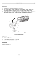
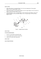
Install new rubber round section (Figure 4, Item 1) in groove (Figure 4, Item 7) of holder (Figure 4, Item 2).
Ends of rubber round section (Figure 4, Item 1) should overlap.
7.
Cut ends of rubber round section (Figure 4, Item 1) at an angle where they meet in groove (Figure 4, Item 7).
Remove rubber round section (Figure 4, Item 1).
8.
Apply adhesive in groove (Figure 4, Item 7) with brush. Put rubber round section (Figure 4, Item 1) in groove
(Figure 4, Item 7) so ends overlap where they are cut.
9.
Put plate spacer (Figure 4, Item 5) on holder (Figure 4, Item 2). Install four screws (Figure 4, Item 4) on
body
(Figure 4, Item 3).
10.
Put holder (Figure 4, Item 2) on body (Figure 4, Item 3). Loosely install five screws (Figure 4, Item 4).
11.
Align four holes (Figure 4, Item 5) in holder (Figure 4, Item 2) with mounting lugs (Figure 4, Item 6) on body
(Figure 4, Item
3
). Tighten five screws (Figure 4, Item 4).
2
2
3
M0012HBF
1
2
7
1
6
5
4
Figure 4.
Headlight Round Rubber Seal Installation.
END OF TASK
FOLLOW-ON MAINTENANCE
1.
Connect negative battery cable (TM 5-2350-262-20).
2.
Unblock front of vehicle (TM 5-2350-262-20).
END OF TASK
END OF WORK PACKAGE
TM 5-2350-377-13&P
0032
0032-4
Back to Top


