TM-5-5420-202-20-2 - Page 206 of 734
TM 5-5420-202-20-2
POWERPLANT LEFT BANK OIL COOLER FRAME AND BRACKETS REPLACEMENT (Sheet 6 of 9)
INSTALLATION:
NOTE
Because of space limitations, it may
be necessary to interchange like size
sockets with wrenches to get at a
particular screw.
7.
8.
9.
10.
11.
1.
2.
3.
4.
5.
6.
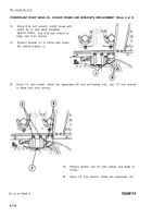
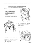
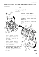
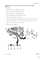
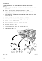
Install screw (A) through bracket (B).
Position bracket (B) and screw (A) on engine.
Install clamp and two shims (C) on screw (A).
Using 9/16 inch socket and 9/16 inch wrench,
install nut (D).
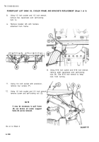
Using 1/2 inch socket with extension, install
nuts (E).
Position bracket (F) on engine.
Using 1/2 inch socket with extension
or 1/2 inch wrench, install nuts (G).
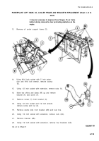
Position clamp (H) on fuel line and
install screw (J) through clamp (H)
and bracket (F).
Using 1/2 inch socket and 1/2 inch
wrench, install nut (K) on screw (J).
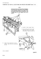
Using 1/2 inch socket with extension,
install four brackets (L).
Position frame support brackets (M) on engine
and, using 11/16 inch socket, install two
new locknuts (N) to secure each frame sup-
port bracket (M).
Go on to Sheet 7
6-131
Back to Top

