TM-5-5420-202-20-2 - Page 468 of 734
TM 5-5420-202-20-2
FUEL-WATER SEPARATOR OPERATIONAL TESTS (Sheet 11 of 11)
Sequential Drain Test (Sheet 4 of 4)
18.
19.
20.
21.
22.
23.
24.
25.
26.
27.
28.
29.
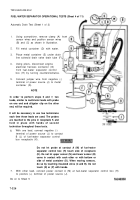
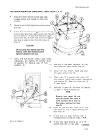
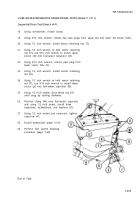
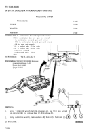
Using screwdriver, install clamp.
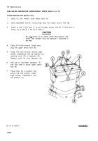
Using 5/16 inch wrench, remove two pipe plugs from upper (A) and lower (S) sensor holes.
Using 1/2 inch wrench, install sensor retaining nut (T).
Using 1/2 inch wrench to hold sensor retaining
nut (T), use 9/16 inch wrench to install upper
sensor (G) into fuel-water separator (D).
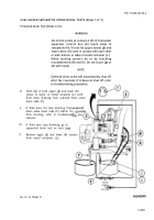
Using 5/16 inch wrench, remove pipe plug from
lower sensor hole (S).
Using 1/2 inch wrench, install sensor retaining
nut (U).
Using 1/2 inch wrench to hold sensor retaining
nut (T), use 9/16 inch wrench to install lower
sensor (J) into fuel-water separator (D).
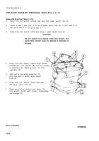
Using 1/2 inch socket, close bleed cap (V)
until snug by turning clockwise.
Position clamp (W) onto fuel-water separator
and, using 1/2 inch socket, install three
capscrews, lockwashers, and washers (X).
Using 1/2 inch socket and extension, tighten
capscrew (Y).
Install powerplant (page 5-14).
Perform fuel system bleeding
procedure (page 7-63).
End of Task
7-233
Back to Top

