TM-5-5420-202-20-3 - Page 582 of 1060
TM 5-5420-202-20-3
SERVOBANDS ADJUSTMENT (Sheet 3 of 3)
6.
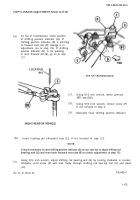
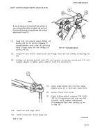
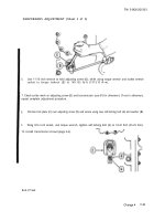
Use 1-1/16 inch wrench to hold adjusting screw (D), while using torque wrench and socket wrench
socket to torque locknut (E) to 145-155 lb-ft (197-210 N·m).
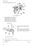
7. Check scribe mark on adjusting screw (D) and transmission case (F) for alinement. If not in alinement,
repeat complete adjustment procedure.
8.
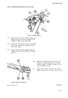
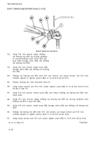
Position lock plate (C) over adjusting screw (D) and secure using new self-locking bolt (A) and washer (B).
9.
Wing 9/16 inch socket, and torque wrench, tighten self-locking bolt (A) to 18-22 lb-ft (25-29 N·m).
10. Install transmission shroud (page 9-6).
End of Task
Change 4
11-85
Back to Top

