TM-5-5420-228-24 - Page 338 of 750
TM 5-5420-228-24
SCISSORS CYLINDER HOSE ASSEMBLIES (CF1, CF2, CG, CI, AND CJ) AND HYDRAULICS
REPLACEMENT (Sheet 3 of 12)
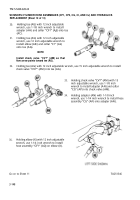
6.
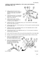
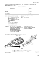
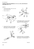
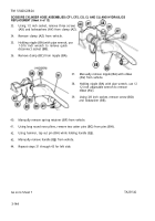
Holding tee (J) with 12 inch adjustable
wrench, use 1-1/8 inch wrench to remove
adapter (D) and collar “CF1” (K) from
tee (J).
7.
Holding tee (J) with 12 inch adjustable
wrench, use other 12 inch adjustable wrench
to remove elbow (G) and collar “CI” (L).
11.
12.
13.
8.
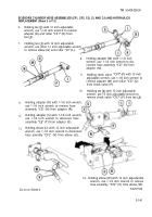
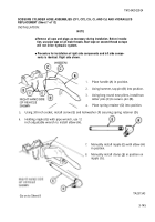
Holding adapter (M) with 1-1/8 inch
wrench, use 1-1/4 inch wrench to dis-
connect hose assembly “CG” (N) from
adapter (M).
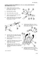
9.
Holding check valve
“CV7” (P) with 15 inch
adjustable wrench, use 1-1/8 inch wrench to
remove adapter (M) and collar “CG” (Q)
from check valve (P).
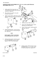
Holding adapter (R) with 1-1/8 inch wrench,
use 1-1/4 inch wrench to remove hose
assembly “CG” (N) from adapter (R).
Holding adapter (S) with 1-1/8 inch wrench,
use 1-1/4 inch wrench to disconnec hose
assembly “CJ” (T) from adapter (S).
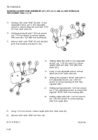
Holding elbow (U) with 12 inch adjustable
wrench, use 1-1/4 inch wrench to disconnect
hose asembly “CF2” (V) from elbow (U).
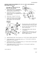
10.
Holding tee (J) with 12 inch adjustable
wrench, use 15 inch adjustable wrench to
remove check valve “CV7” (P) from tee (J).
14.
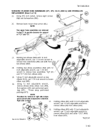
Holding elbow (W) with 12 inch adjustanble
wrench, use 1-1/4 inch wrench to remove
hose assembly “CF2” (V) from elbow (W).
Go on to Sheet 4
TA251539
3-141
Back to Top

