TM-5-5420-228-24 - Page 336 of 750
TM 5-5420-228-24
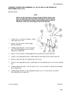
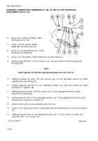
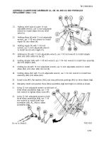
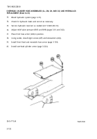
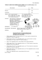
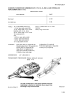
SCISSORS CYLINDER HOSE ASSEMBLIES (CF1, CF2, CG, CI, AND CJ) AND HYDRAULICS
REPLACEMENT (Sheet 1 of 12)
PROCEDURE INDEX
PROCEDURE
PAGE
Removal
3-139
Installation
3-145
TOOLS:
12 in. adjustable wrench (2)
9/16 in. socket with 1/2 in. drive
1-1/4 in. open end wrench (2)
Hammer
1/2 in. socket with 1/2 in. drive
Pliers, long round nose
Ratchet with 1/2 in. drive
3/8 in. socket with 1/2 in. drive
14 in. pipe wrench
Vise
1-5/16 in. open end wrench
1-1/8 in. open end wrench
1-3/8 in. open end wrench
15 in. adjustable wrench
SUPPLIES:
Pipe tape (Item 19, Appendix D)
Lockwashers (2 required)
Masking tape (Item 18, Appendix D)
Preformed packings (2 required)
Pencil (Item 22, Appendix D)
Cotter pins (4 required)
Rags (Item 12, Appendix D)
Drip pans (suitable containers)
Protective caps and plugs
REFERENCES:
LO 5-5420-202-12
PRELIMINARY PROCEDURE: Relieve hydraulic pressure
(page 3-71)
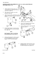
NOTE
Use rags and drip pans to catch excess hydraulic fluid. Use
masking tape to tag lines for installation. Cap or plug all lines
TA251537
3-139
Go on to Sheet 2
and fittings as they are disconnected.
Back to Top

