TM-5-5420-228-24 - Page 343 of 750
TM 5-5420-228-24
SCISSORS CYLINDER HOSE ASSEMBLIES (CF1, CF2, CG, CI, AND CJ) AND HYDRAULICS
REPLACEMENT (Sheet 8 of 12)
9.
10.
11.
15.
16.
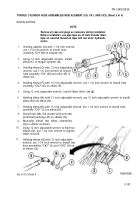
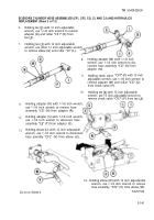
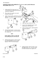
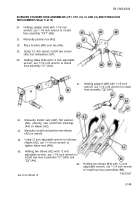
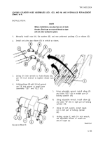
Holding nipple (G) with pipe wrench, use 1-
5/16 inch wrench to install quick disconnect’
socket (K) to nipple (G).
Place clamp (L) in position over quick
disconnect socket (K).
Using 1/2 inch socket, install three screws
(M) and lockwashers (N) securing clamps (J)
and (L).
12.
13.
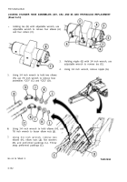
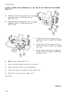
Holding nipple (R) with 1-1/8 inch wrench,
use 1-3/8 inch wrench to install bushing (S)
onto nipple (R).
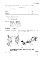
NOTE
Install regulator “PCV3” (T) with flow
arrow pointing away from relief valve (P).
Holding bushing (S) with 1-3/8 inch wrench.
14.
use 15 inch adjustable wrench to install
regulator “PCV3” (T) onto bushing (S).
Place relief valve “RV8” (P) in vise.
Using 12 inch adjustable wrench, install
elbow (Q) into relief valve (P).
Using 1-1/8 inch wrench, install nipple (R)
into relief valve (P).
17.
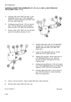
Holding regulator “PCV3” (T) with 15 inch
adjustable wrench, use 1-3/8 inch wrench
to install bushing (U) into regulator (T).
G
O
on to Sheet 9
3-146
TA251544
Back to Top


