TM-9-2320-272-23-2 - Page 1020 of 1417
INSTALLATION - Continued
9.
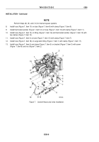
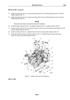
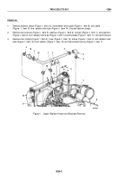
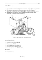
Install hose (Figure 4, Item 13), elbow (Figure 4, Item 4), and radiator inlet tube (Figure 4, Item 14) on radiator
(Figure 4, Item 10) and thermostat housing (Figure 4, Item 7) with four clamps (Figure 4, Item 3).
10.
Install radiator inlet tube (Figure 4, Item 14) on bracket (Figure 4, Item 11) with two washers
(Figure
4,
Item
2), screws (Figure 4, Item 1), washers (Figure 4, Item 6), and locknuts (Figure 4, Item 5).
11.
Secure tachometer drive cable (Figure 4, Item 8) and cable (Figure 4, Item 9) to radiator inlet tube
(Figure
4,
Item 14) with tiedown straps (Figure 4, Item 12).
M9723DAA
14
1
2
5
6
3
3
3
7
11
12
8
9
10
4
13
3
Figure 4.
Upper Radiator Hoses and Brackets Installation.
END OF TASK
FOLLOW-ON MAINTENANCE
1.
Connect fan actuator. (Volume 3, WP
0448)
2.
Fill cooling system. (WP
0287)
3.
Install right splash shield. (TM 9-2320-272-10)
4.
Hood closed and secured. (TM 9-2320-272-10)
5.
Start engine and check for leaks. (TM 9-2320-272-10)
END OF TASK
END OF WORK PACKAGE
TM 9-2320-272-23-2
0286
0286-5/6 blank
Back to Top

