TM-9-2320-272-23-2 - Page 1014 of 1417
INSTALLATION - Continued
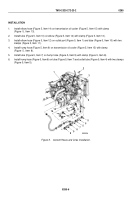
14.
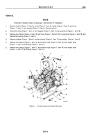
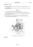
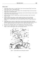
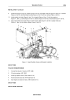
Install hose (Figure 8, Item 14) on heater valve (Figure 8, Item 15) and fitting (Figure 8, Item 17) with two
clamps (Figure 8, Item 11).
15.
Install hose (Figure 8, Item 13) on heater valve (Figure 8, Item 16) and fitting (Figure 8, Item 10) with two
clamps (Figure 8, Item 12).
NOTE
Wrap male pipe threads with antiseize tape before installation.
16.
Install two elbows (Figure 8, Item 7) and adapter (Figure 8, Item 4) on radiator (Figure 8, Item 8).
17.
Install hose (Figure 8, Item 20) on surge tank (Figure 8, Item 18) and thermostat housing (Figure 8, Item 9)
with two clamps (Figure 8, Item 19).
18.
Install hose (Figure 8, Item 1) on adapter (Figure 8, Item 4) and surge tank (Figure 8, Item 18).
19.
Install clamp (Figure 8, Item 3) and hose (Figure 8, Item 1) on bracket (Figure 8, Item 6) with screw
(Figure
8,
Item 2) and locknut (Figure 8, Item 5).
7
8
9
10
11
12
13
14
12
11
15
16
17
18
19
20
6
5
4
3
2
1
M9583DAA
Figure 8.
Coolant Hoses and Lines Installation.
END OF TASK
TM 9-2320-272-23-2
0285
0285-9
Back to Top

