TM-9-2320-272-23-2 - Page 1004 of 1417
RETURN TUBE INSTALLATION - Continued
3.
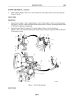
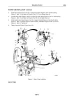
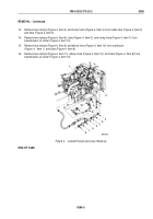
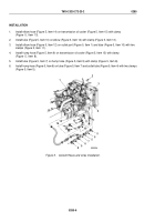
Install return tube (Figure 4, Item 5) on compressor elbow (Figure 4, Item 15) with bushing
(Figure
4,
Item
14) and flare nut (Figure 4, Item 13). Do not tighten flare nut.
4.
Connect return tube (Figure 4, Item 5) on engine oil cooler elbow (Figure 4, Item 11) with bushing
(Figure
4,
Item
10) and flare nut (Figure 4, Item 9). Do not tighten flare nut.
5.
Install coolant return tube (Figure 4, Item 5) on support bracket (Figure 4, Item 4) with clamp
(Figure
4,
Item
3), washers (Figure 4, Items 2 and 8), lockwasher (Figure 4, Item 7), and nut
(Figure
4,
Item
6). Tighten nut.
6.
Tighten flare nuts (Figure 4, Items 9 and 13).
8
M0126DAA
7
6
1
4
2 3
5
12
10
9
5
11
16
15
14
13
5
16
5
Figure 4.
Return Tube Installation.
END OF TASK
TM 9-2320-272-23-2
0284
0284-5
Back to Top

