TM-9-2320-272-23-2 - Page 1003 of 1417
SUPPLY TUBE INSTALLATION
NOTE
Male pipe threads must be wrapped with antiseize tape before installation.
1.
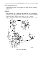
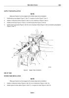
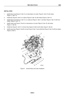
Install water pump adapter (Figure 3, Item 7) in engine oil cooler (Figure 3, Item 1).
2.
Install air compressor elbow (Figure 3, Item 2) on air compressor (Figure 3, Item 3).
3.
Install two bushings (Figure 3, Item 4) in coolant supply tube (Figure 3, Item 6).
4.
Install coolant supply tube (Figure 3, Item 6) on air compressor elbow (Figure 3, Item 2) and water pump adapter
(Figure 3, Item 7).
2
M0125DAA
3
4
5
5
6
4
1
7
Figure 3.
Supply Tube Installation.
END OF TASK
RETURN TUBE INSTALLATION
NOTE
Male pipe threads must be wrapped with antiseize tape before installation.
1.
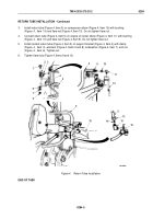
Install air compressor elbow (Figure 4, Item 15) on air compressor (Figure 4, Item 16).
2.
Install engine oil cooler elbow (Figure 4, Item 11) on engine oil cooler (Figure 4, Item 12).
TM 9-2320-272-23-2
0284
0284-4
Back to Top


