TM-9-2320-272-23-2 - Page 1008 of 1417
REMOVAL - Continued
7.
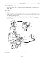
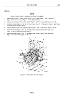
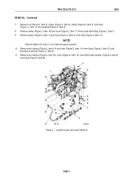
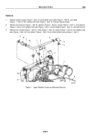
Remove nut (Figure 2, Item 2), screw (Figure 2, Item 6), clamp (Figure 2, Item 5), and hose
(Figure
2,
Item
4) from bracket (Figure 2, Item 3).
8.
Remove clamp (Figure 2, Item 16) and hose (Figure 2, Item 17) from surge tank fitting (Figure 2, Item 1).
9.
Remove clamp (Figure 2, Item 7) and hose (Figure 2, Item 4) from tube (Figure 2, Item 14).
NOTE
Perform Steps (10) and (11) for internal bypass systems.
10.
Remove two clamps (Figure 2, Item 10) and hose (Figure 2, Item 11) from fitting (Figure 2, Item 15) and
thermostat canister (Figure 2, Item 9).
11.
Remove two clamps (Figure 2, Item 12), hose (Figure 2, Item 13), and thermostat canister (Figure 2, Item 9)
from tube (Figure 2, Item 8).
2
3
4
5
6
7
12
14
8
9
10
11
10
12
13
15
16
17
1
M9584DAA
Figure 2.
Coolant Hoses and Lines Removal.
TM 9-2320-272-23-2
0285
0285-3
Back to Top


