TM-9-2320-272-23-2 - Page 421 of 1417
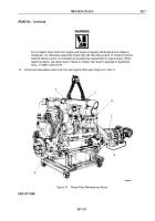
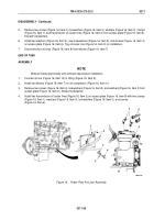
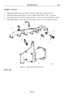
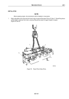
REMOVAL - Continued
NOTE
Front of cab must be raised 4 in. (102 mm) to permit engine oil pan sump to clear the front
axle differential housing. Two permanently mounted jack screws under the left and right cab
A-posts permit raising front of cab.
2.
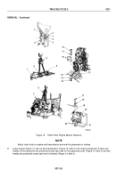
Remove two locknuts (Figure 13, Item 5), washers (Figure 13, Item 4), and rubber cushions
(Figure
13,
Item
3) from cab A-post support brackets (Figure 13, Item 2). Discard locknuts.
3.
Turn left and right jack screws (Figure 13, Item 6) until A-posts (Figure 13, Item 1) are approximately 4 in.
(102
mm) above support brackets (Figure 13, Item 2).
WARNING
Lifting device must have a weight capacity greater than the combined weight of the engine
and transmission. Failure to comply may result in damage to equipment, injury, or death to
personnel.
4.
Attach the adjustable end of an adjustable chain hoist (Figure 13, Item 9) to hoist hook and each adjustable
chain hoist hook to engine lifting eyes (Figure 13, Item 8). Raise hoist until all slack is removed from adjustable
chain hoist, ensuring that hoist does not support weight of engine (Figure 13, Item 7).
5.
Remove two screws (Figure 13, Item 12), lockwashers (Figure 13, Item 11), five screws (Figure 13, Item 14),
lockwashers (Figure 13, Item 15), trunnion cap (Figure 13, Item 10), and trunnion mount (Figure 13, Item 13)
from frame crossmember (Figure 13, Item 16). Discard lockwashers.
6.
Remove two nuts (Figure 13, Item 21), lockwashers (Figure 13, Item 22), screws (Figure 13, Item 17), and
washers (Figure 13, Item 18) from left and right engine supports (Figure 13, Item 20) and flywheel housing
(Figure 13, Item 19). Discard lockwashers.
TM 9-2320-272-23-2
0211
0211-24
Back to Top

