TM-9-2320-272-23-2 - Page 426 of 1417
DISASSEMBLY - Continued
5.
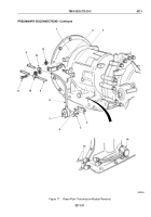
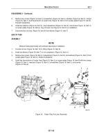
Remove two screws (Figure 16, Item 4), lockwashers (Figure 16, Item 5), washers (Figure 16, Item 3), clamps
(Figure 16, Item 1), and transmission oil cooler lines (Figure 16, Item 2) from access plate (Figure 16, Item 6).
Discard lockwashers.
6.
Install two washers (Figure 16, Item 3), new lockwashers (Figure 16, Item 5), and screws (Figure 16, Item 4)
on access plate (Figure 16, Item 6). Tag oil cooler line (Figure 16, Item 2) for installation.
7.
Disconnect two air lines (Figure 16, Item 8) from elbows (Figure 16, Item 7).
END OF TASK
ASSEMBLY
NOTE
Wrap all male pipe threads with antiseize tape before installation.
1.
Connect air line (Figure 16, Item 10) to fitting (Figure 16, Item 9).
2.
Install two elbows (Figure 16, Item 7) on air compressor (Figure 16, Item 11).
3.
Remove two screws (Figure 16, Item 4), lockwashers (Figure 16, Item 5), and washers (Figure 16, Item 3) from
access plate (Figure 16, Item 6). Discard lockwasher.
4.
Install two transmission oil cooler lines (Figure 16, Item 2) on access plate (Figure 16, Item 6) with two clamps
(Figure 16, Item 1), washers (Figure 16, Item 3), lockwashers (Figure 16, Item 5), and screws
(Figure 16, Item 4).
M9371DAA
7
1
8
9
10
11
4
5
6
3
2
Figure 16.
Power Plant Air Lines Assembly.
TM 9-2320-272-23-2
0211
0211-29
Back to Top


