TM-9-2320-272-23-2 - Page 429 of 1417
INSTALLATION - Continued
WARNING
Personnel not participating in engine removal must stand clear during hoisting operations. A
snapped cable, or swinging or shifting load, may occur. Failure to comply may result in injury
or death to personnel.
CAUTION
Lower engine and transmission into chassis carefully and closely observe all engine and
transmission components to prevent damage to equipment. Always remove engine slowly.
NOTE
•
For Steps (2) through (4), if engine is removed in the field, an additional assistant will be
needed to operate the wrecker crane. Shop removal of engine requires a mechanic and
one assistant if overhead hoist is available.
•
Chain hoist must be adjusted so transmission points downward at approximately a
15
to
20°
angle for engine to clear front axle.
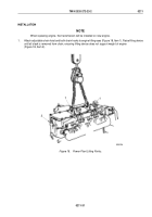
2.
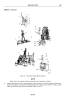
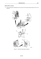
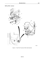
Install trunnion mount (Figure 19, Item 6) on frame crossmember (Figure 19, Item 9) with five lockwashers
(Figure 19, Item 8) and screws (Figure 19, Item 7). Do not tighten screws.
3.
Raise engine (Figure 19, Item 1) and transmission (Figure 19, Item 2) over front bumper (Figure 19, Item 4)
directly above engine compartment (Figure 19, Item 3).
4.
Using socket wrench, adjust engine angle to 15° to 20° with adjustable ratchet on lifting device.
5.
Slowly lower engine (Figure 19, Item 1) and transmission (Figure 19, Item 2) into engine compartment
(Figure
19,
Item
3).
6.
Lower engine (Figure 19, Item 1) and transmission (Figure 19, Item 2) until resting on trunnion mount
(Figure
19,
Item
6) and left and right rear engine supports (Figure 19, Item 15).
7.
Using a drift pin, align holes in left and right rear engine supports (Figure 19, Item 15) and engine flywheel
housing (Figure 19, Item 14), and install two washers (Figure 19, Item 13), screws (Figure 19, Item 12),
lockwashers (Figure 19, Item 17), and nuts (Figure 19, Item 16). Tighten nuts 140 to 160 lb-ft
(190
to
217
N·m).
8.
Install transmission (Figure 19, Item 18) on rear support bracket (Figure 19, Item 21) with two lockwashers
(Figure 19, Item 20) and screws (Figure 19, Item 19). Tighten screws 75 to 85 lb-ft (102 to 115 N·m).
9.
Turn left and right jack screws (Figure 19, Item 27) until rubber cushions (Figure 19, Item 28) of A-posts
(Figure
19, Item 22) rest on A-post support brackets (Figure 19, Item 23). Ensure jack screws are turned all
the way down in A-post support brackets.
10.
Install cab A-posts (Figure 19, Item 22) on each A-post support bracket (Figure 19, Item 23) with rubber
cushions (Figure 19, Item 24), washer (Figure 19, Item 25), and locknut (Figure 19, Item 26).
11.
Install trunnion cap (Figure 19, Item 10) on trunnion mount (Figure 19, Item 6) with two lockwashers
(Figure
19, Item 11) and screws (Figure 19, Item 5). Tighten screws 150 lb-ft (203 N·m).
12.
Tighten screws (Figure 19, Item 7) 65 to 75 lb-ft (88 to 102 N·m).
TM 9-2320-272-23-2
0211
0211-32
Back to Top

