TM-9-2320-272-23-3 - Page 495 of 1469
REMOVAL
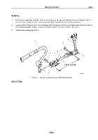
1.
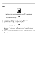
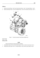
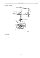
Remove two screws (Figure 1, Item 5) and interlock valve (Figure 1, Item 1) from bracket (Figure 1, Item 4).
2.
Remove three elbows (Figure 1, Item 2) and adapter (Figure 1, Item 3) from interlock valve (Figure 1, Item 1).
3
4
5
2
1
2
2
M7039DAA
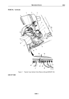
Figure 1.
Transfer Case Interlock Valve Removal (M936/A1/A2).
END OF TASK
INSTALLATION
NOTE
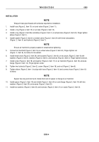
Wrap all male threads with antiseize tape before installation.
1.
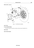
Install adapter (Figure 2, Item 3) and three elbows (Figure 2, Item 2) on interlock valve (Figure 2, Item 1).
2.
Install interlock valve (Figure 2, Item 1) on bracket (Figure 2, Item 4) with two screws (Figure 2, Item 5).
TM 9-2320-272-23-3
0395
0395-2
Back to Top

