TM-9-2320-272-23-4 - Page 1077 of 1393
REMOVAL
CAUTION
Plug all hydraulic hoses to prevent dirt from entering.
NOTE
•
Front and rear winch control valves are replaced basically the same. This procedure
covers the front winch control valve.
•
Tag all hoses and fittings for installation.
1.
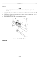
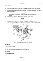
Disconnect hoses (Figure 1, Items 2, 4, 5, 6, 7, and 17) from control valve (Figure 1, Item 8).
NOTE
Both upper and lower cable clevises are removed the same way.
2.
Remove cotter pin (Figure 1, Item 15), washer (Figure 1, Item 14), and clevis pin (Figure 1, Item 3) from two
cable clevises (Figure 1, Item 1). Discard cotter pin.
3.
Remove three locknuts (Figure 1, Item 13), screws (Figure 1, Item 12), and control valve (Figure 1, Item 8)
from bracket (Figure 1, Item 10). Discard locknuts.
4.
Remove four nuts (Figure 1, Item 9), screws (Figure 1, Item 11), and bracket (Figure 1, Item 10) from frame
(Figure 1, Item 16).
3
4
5
M6027DAA
1
2
6
7
8
9
10
11
12
13
14
15
16
1
17
Figure 1.
Front and Rear Winch Control Valve Removal.
TM 9-2320-272-23-4
0721
0721-2
Back to Top


