TM-9-2320-272-23-4 - Page 1079 of 1393
INSTALLATION
1.
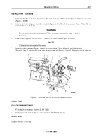
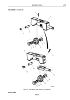
Install six o-rings (Figure 3, Item 12), fittings (Figure 3, Items 1, 4, and 14), and elbows
(Figure
3,
Items
3
and
11) on control valve (Figure 3, Item 13). Position as noted in removal.
2.
Install elbows (Figure 3, Items 2 and 5) and adapter (Figure 3, Item 10) on valve fittings
(Figure
3,
Items
1
and
4) and elbow (Figure 3, Item 11).
3.
Install relief valve (Figure 3, Item 9), spring (Figure 3, Item 8), o-ring (Figure 3, Item 7), and plug
(Figure
3,
Item
6) in control valve (Figure 3, Item 13).
3
4
5
M9945DAA
1
2
12
15
12
6
7
8
9
10
11
12
13
12
14
Figure 3.
Front and Rear Winch Control Valve Installation.
TM 9-2320-272-23-4
0721
0721-4
Back to Top

