TM-9-2320-272-23-4 - Page 1080 of 1393
INSTALLATION
- Continued
4.
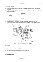
Install bracket (Figure 4, Item 10) on frame (Figure 4, Item 16) with four screws (Figure 4, Item 11) and nuts
(Figure 4, Item 9).
5.
Install control valve (Figure 4, Item 8) on bracket (Figure 4, Item 10) with three screws (Figure 4, Item 12) and
locknuts (Figure 4, Item 13).
WARNING
Do not cross hoses during installation. Failure to comply may result in injury or death to
personnel.
6.
Install hoses (Figure 4, Items 2, 4, 5, 6, 7, and 17) on control valve (Figure 4, Item 8).
NOTE
Cable clevises are installed the same.
7.
Install two cable clevises (Figure 4, Item 1) on control valve (Figure 4, Item 8) rod with clevis pin
(Figure
4,
Item
3), washer (Figure 4, Item 14), and cotter pin (Figure 4, Item 15). Bend over end of cotter pin.
3
4
5
M9946DAA
1
2
6
7
8
9
10
11
12
13
14
15
16
1
17
Figure 4.
Front and Rear Winch Control Valve Installation.
END OF TASK
FOLLOW-ON MAINTENANCE
1.
Fill hydraulic oil reservoir. (Volume 5, WP
0820)
2.
Start engine and check hydraulic pump operation. (TM 9-2320-272-10)
END OF TASK
END OF WORK PACKAGE
TM 9-2320-272-23-4
0721
0721-5/6 blank
Back to Top

