TM-9-2320-272-23-4 - Page 1089 of 1393
ASSEMBLY - Continued
10.
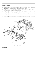
Install bracket (Figure 4, Item 8) on rear winch (Figure 4, Item 3) with four washers (Figure 4, Item 11), screws
(Figure 4, Item 12), lockwashers (Figure 4, Item 5), and nuts (Figure 4, Item 4).
11.
Install tensioner frame (Figure 4, Item 14) on bracket (Figure 4, Item 8) with two screws (Figure 4, Item 6),
lockwashers (Figure 4, Item 2), and nuts (Figure 4, Item 1).
12.
Install bracket (Figure 4, Item 15) on tensioner frame (Figure 4, Item 14) with two screws (Figure 4, Item 18),
lockwashers (Figure 4, Item 19), and nuts (Figure 4, Item 20).
13.
Install bracket (Figure 4, Item 15) on rear winch (Figure 4, Item 3) with lockwasher (Figure 4, Item 17) and
screw (Figure 4, Item 16).
14.
Install lever (Figure 4, Item 7) on bracket (Figure 4, Item 8) and rod of frame (Figure 4, Item 14) with two pins
(Figure 4, Items 9 and 13) and four cotter pins (Figure 4, Item 10).
7
M6037DAA
6
5
4
8
9
10
13
10
14
15
16
17
18
19
20
1
2
3
12
11
Figure 4.
Rear Winch Assembly.
END OF TASK
TM 9-2320-272-23-4
0722
0722-8
Back to Top


