TM-9-2320-272-23-4 - Page 1097 of 1393
REMOVAL
WARNING
Ensure dump control lever is in the NEUTRAL position and has not moved. Failure to comply
may result in injury or death to personnel.
NOTE
A 4x4 block of wood is recommended for use as support.
1.
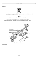
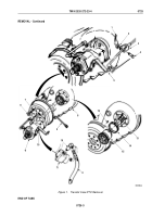
Raise hoist cylinders (Figure 1, Items 4 and 10) from subframe (Figure 1, Item 5) and place wood support
(Figure 1, Item 3) between subframe (Figure 1, Item 5) and cylinders (Figure 1, Items 4 and 10).
2.
Remove four screws (Figure 1, Item 2), lockwashers (Figure 1, Item 1), two upper crosshead retainers
(Figure
1,
Item
6), lower cross head retainers (Figure 1, Item 8), and crosshead (Figure 1, Item 9) from two
piston rods (Figure 1, Item 7). Discard lockwashers.
M10230DAA
1
2
3
4
5
6
7
8
9
10
Figure 1.
Dump Hoist Cylinder Removal.
TM 9-2320-272-23-4
0724
0724-2
Back to Top


