TM-9-2320-272-23-4 - Page 1078 of 1393
REMOVAL
- Continued
5.
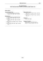
Remove elbows (Figure 2, Items 2 and 5) and adapter (Figure 2, Item 10) from valve fittings
(Figure
2,
Items
1
and
4) and elbow (Figure 2, Item 11).
6.
Remove fittings (Figure 2, Items 1, 4, and 14) and elbows (Figure 2, Items 3, 11, and 15) from control valve
(Figure 2, Item 13).
7.
Remove six o-rings (Figure 2, Item 12) from fittings (Figure 2, Items 1, 4, and 14) and elbows
(Figure
2,
Items
3
and
11). Discard o-rings.
8.
Remove plug (Figure 2, Item 6), o-ring (Figure 2, Item 7), spring (Figure 2, Item 8), and relief valve
(Figure
2,
Item
9) from control valve (Figure 2, Item 13). Discard o-ring.
3
4
5
M6028DAA
1
2
12
15
12
6
7
8
9
10
11
12
13
12
14
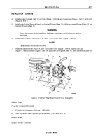
Figure 2.
Front and Rear Winch Control Valve Removal.
END OF TASK
TM 9-2320-272-23-4
0721
0721-3
Back to Top

