TM-9-2320-273-34 - Page 309 of 801
TM9-2320-273-34
(10)
(11)
holds it.
(12)
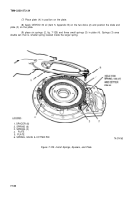
Install six spacers (1).
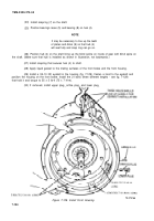
Place the valve and spring (6) in position on plate (5) and install the cotter pin that
NOTE
Check that the springs stay in place (in
the vertical position) when the plate is
installed in the next step.
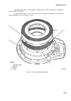
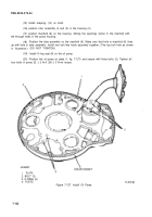
Place plate (5) in position on the springs and spacers. Make sure that hole in base lines up
with valve and spring (6). Install the four bolts that hold the plate – a few turns at a time on each – until
all bolts are turned down; then tighten to 36 ± 2 Ib-ft (46 ± 3 N-m) torque,
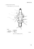
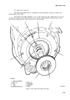
(13) Put key (2, fig. 7-126) on shaft; then slide shaft (1) through housing (3).
(14) If the strainer (8) was removed from the tube assembly (7), install.
LEGEND:
6. MANIFOLD
1.
SHAFT
7. TUBE ASSEMBLY
2. KEY
8. STRAINER
3. HOUSING
9. O-RING SEAL
4.
ROTOR ASSEMBLY 10. SNAP RING
5. ROTOR ASSEMBLY 11. KEY
Figure 7-126. Assemble Oil Pump.
TA 074131
7-131
Back to Top


