TM-9-2320-273-34 - Page 310 of 801
TM9-2320-273-34
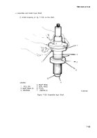
(15) Install snapring (10) on shaft.
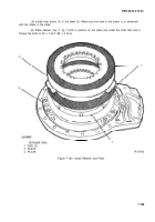
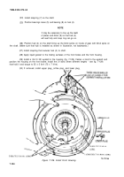
(16) position rotor assembly (4 and (5) in the housing (3).
(17) position manifold (6) on the housing. Alining the openings (slots) in the manifold with
the through holes in the pump housing.
(18)
up with hole in
in illustration.)
(19)
(20)
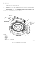
Position the tube assembly on the manifold (6). Make sure that hole in manifold (6) lines
tube assembly. Install one bolt that holds assembly together. (The top bolt hole as shown
(DO NOT TIGHTEN.)
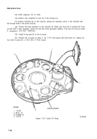
Install O-ring seal (9) on the oil pump.
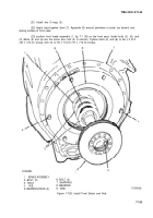
Position the oil pump on plate (1, fig. 7-127) and secure with three bolts (2). Tighten all
four bolts in pump 22 ± 2 Ib-ft (28 ± 3 N-m) torque.
LEGEND:
1.
PLATE
2. BOLT (3)
3. O-RING (2)
4. PLATE
Figure 7-127. Install Oil Pump.
TA 074164
7-132
Back to Top


