TM-9-2320-273-34 - Page 434 of 801
TM 9-2320-273-34
(6)
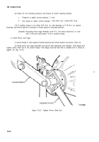
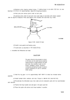
Install the second side gear and thrust washer.
(7)
Position the other case half over the assembly, alining match marks of both halves. Draw
—
the assembly together with three equally spaced capscrews.
(8)
Install the remaining capscrews and torque to 85-115 Ib-ft(115-156 N·m).
(9)
If new bearings are to be used, press squarely and firmly on the differential case halves with
a suitable sleeve.
d. Rolling Resistance of Differential Nest.
(1)
Place the differential and ring gear assembly in a vise with soft metal jaws.
(2)
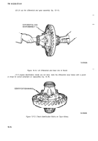
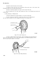
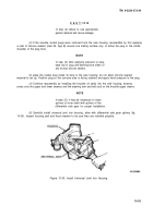
Insert a checking tool (made from a splined axle shaft end) into the differential nest
(fig.
10-23).
Allow the splines of the tool to engage with the spline of one side gear only.
Figure 10-23. Install Checking Tool.
(3)
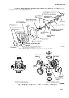
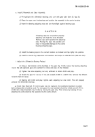
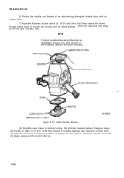
Using a suitable socket and torque wrench, rotate the differential nest while observing the
scale on the torque wrench (fig. 10-24). Correct rolling resistance of the differential assembly is 50 Ib-ft
(68 N·m) torque maximum applied to one side gear.
Figure 10-24. Check Rolling Resistance.
10-26
Back to Top

