TM-9-2320-273-34 - Page 435 of 801
TM 9-2320-273-34
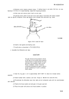
e. Install Differential and Gear Assembly.
(1)
Pre-lubricate the differential bearings and
CUPS
with gear lube (item 30, App B).
(2)
Place the cups over the bearings and position the assembly in the carrier housing.
(3)
Insert the bearing adjusting nuts and turn hand-tight against bearing cups.
CAUTIO N
If bearing caps do not position properly,
adjusting nuts might be cross-threaded.
Remove caps and reposition the adjusting
nuts. Forcing the caps into position will
result in irreparable damage to the carrier
housing or bearing caps.
(4)
Install the bearing caps in the correct location as marked and tap lightly into position.
(5)
Install the carrier leg capscrews and washers and torque to 290-350 Ib-ft (393-475 N·m).
f. Adjust the Differential Bearing Preload.
(1)
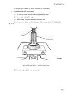
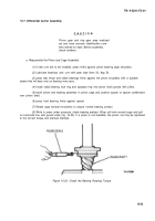
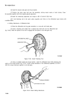
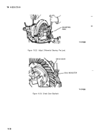
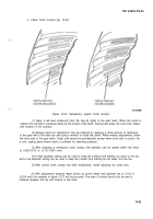
Using a dial indicator at the backface of the gear (fig. 10-25), loosen the bearing adjusting
nut on
the side opposite gear on/y
sufficient to notice end play on the indicator.
(2)
Tighten the same adjusting nut only sufficient to obtain 0.000 end play.
(3)
Check the gear for run-out. If run-out exceeds 0.008 in. (0.203 mm), remove the differen-
tial and check for cause.
(4)
Starting with 0.000 end play, tighten each adjusting nut one notch. This will properly
preload the differential bearings.
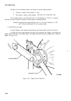
g. Check Gear Back/ash.
If the drive gear was not replaced, the established backlash recorded
before disassembly should be used. For new gears the new backlash should be initially set at 0.010 in.
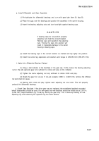
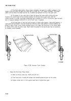
(0.254 mm). Adjust backlash (fig. 10-26) by moving the gear only. This is done by backing off one
adjusting ring and advancing the opposite ring the same amount.
10-27
Back to Top

