TM-9-2320-273-34 - Page 438 of 801
TM 9-2320-273-34
(7)
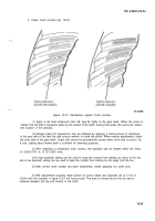
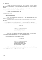
The hand-rolled pattern shown (gears unloaded), will result in a pattern centered in the
length of the tooth when the gears are under load, as shown (fig. 10-27) (gears unloaded). The loaded
pattern will be almost full length and the top of pattern will approach the top of the gear tooth.
(8)
The pattern on the coast side of teeth will appear the same width as the drive side;
however, the overall length will be centered between the toe and heel of gear tooth. After the
correct contacts, as shown, have been established with a backlash of 0.010 in. (0.254 mm), open the back-
lash to measure between 0.005-0.015 in. (0.127-0.381 mm), if required.
(9)
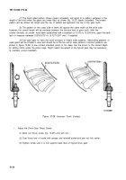
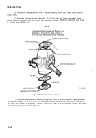
Set used gear to have the tooth contacts to match wear patterns. Hand-rolled patterns of
used gears will be smaller in area and should be at the toe end of wear patterns. Incorrect patterns are
shown in figure 10-28. A low contact indicates pinion is too deep. Set the pinion to the correct depth
by adding shims under the pinion cage. Slight inward movement of the hypoid gear may be necessary
to maintain correct backlash.
Figure 10-28. Incorrect Tooth Contact.
i.
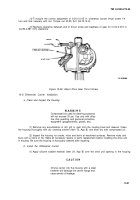
Adjust the Drive Gear Thrust Screw.
(1)
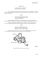
Back out thrust screw (fig. 10-29) and jam nut.
(2)
Coat thrust end of screw with grease and reinstall screw and jam nut into carrier.
(3)
Tighten screw until it is firm against back face of hypoid drive gear.
10-30
Back to Top

