TM-9-2320-273-34 - Page 445 of 801
TM 9-2320-273-34
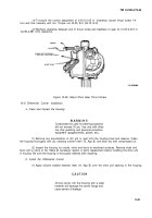
f. Adjust the Wheel Bearing.
(1)
Assemble hub assembly onto spindle, being careful not to damage oil seal in hub. Press
hub until inner bearing is seated flush on the spindle.
(2)
place outer bearing cone in position on the spindle and against its cup in the hub. Adjust
bearings using the following procedures:
(a)
Assemble and tighten bearing adjusting nut onto spindle and against outer bearing.
Tighten nut to 50 Ib-ft (68 N·m) torque while hub is rotated in both directions to seat bearings.
(b)
Back off adjusting nut 1/6-1 /4 turn.
(c)
Assemble nut lock (retainer) and jam nut onto spindle and against adjusting nut.
Torque jam nut 250-400 Ib-ft (340-540 N·m).
g. Reassemble Drum and Drive Flange.
(1)
Install drum over hub pilot. Install drum to hub by installing five flathead capscrews.
Tighten capscrews to 15-30 Ib-ft (20-40 N·m) torque.
(2)
Coat inside hub mating surface of drive flange with silicone sealant.
(3)
Apply wheel bearing grease to internal splines of drive flange and external splines of outer
universal joint shaft.
(4)
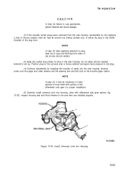
Assemble the drive flange onto hub and secure with washers and capscrews. Torque
capscrews to 180-230 Ib-ft (244-312 N·m).
h. Reassemble the Cross Tube onto Knuckle.
(1)
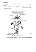
Insert cross tube end assembly shaft through bottom of bore in knuckle arm.
(2)
Secure cross tube to knuckle by assembling slotted nut to ball stud through knuckle
flange. Torque nut to 165-230 Ib-ft (224-312 N·m), Then advance nut to next available cotter pin slot.
Final torque should be no more than 300 Ib-ft (407 Nom) maximum. Insert cotter pin.
(3)
Complete reassembly procedures by assembling wheel (rim and tire) to hub.
i. Adjust the Wheel Toe-/n. (Refer
to TM 9-2320-273-20 for procedure. )
10-37/10-38 (Blank)
Back to Top

