TM-9-2320-280-20-3 - Page 600 of 1168
12-9. SELECTOR VALVE REPLACEMENT
This task covers:
a. Removal
b. Installation
a. Removal
1.
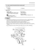
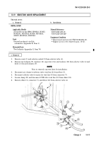
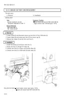
Remove screw (1) and selector control (2) from selector valve (4).
2.
Remove two locknuts (9), washers (13), capscrews (14), and washers (13) from selector valve (4) and
body (3). Discard locknuts (9).
NOTE
Prior to removal, tag vent lines for installation.
3.
Disconnect air cleaner-to-selector valve vent line (6) from elbow (5).
4.
Disconnect selector valve-to-union tee vent line (8) from connector (7).
5.
Loosen clamp (11) and disconnect CDR valve vent line (10) from elbow (12).
6.
Remove elbow (5), connector (7), and elbow (12) from selector valve (4).
INITIAL SETUP:
Applicable Models
All models except M966, M966A1, M1025,
M1025A1, M1025A2, M1026, M1026A1,
M1097, M1097A1, M1097A2
Tools
General mechanic’s tool kit:
automotive (Appendix B, Item 1)
Materials/Parts
Two locknuts (Appendix G, Item 70)
Manual References
TM 9-2320-280-10
TM 9-2320-280-24P
Equipment Condition
• Hood raised and secured (TM 9-2320-280-10).
• Engine access cover removed (para. 10-15).
TM 9-2320-280-20-3
Change 2
12-11
1
2
3
4
5
6
7
8
9
10
11
12
13
13
14
~
Back to Top

