TM-9-2320-328-13-P-1 - Page 844 of 1318
TM 9-2320-328-13&P-1
0076-6
DRAFT
0076
HWT2027
Step 10.
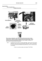
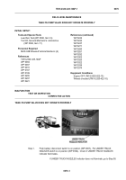
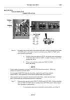
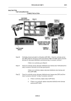
Pull battery disconnect switch to off position (WP 0007).
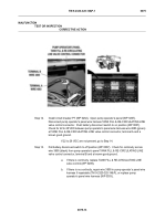
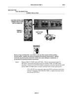
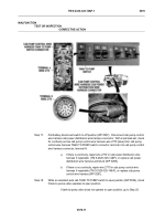
While an assistant holds TANK
TO PUMP switch in on position, check for continuity across TANK TO PUMP switch,
from terminal 5 to terminal 6.
a.
If there is continuity, repair wire 2855 in cab pump control wire harness
if repairable (TM 9-2320-325-14&P), or replace cab pump control wire
harness (WP 0281).
b.
If there is no continuity, replace cab TANK TO PUMP
switch (WP 0199).
NOTE
•
Ensure system air pressure is at least 85 psi (586 kPa) during this procedure.
System air
pressure is required to activate valves.
•
Do not engage PUMP PTO during this procedure, except when performing complete
system checks.
Valve operations can be checked without water pump operation.
•
Valve operations can be checked by observing valve shaft rotation.
Valves are open when
tabs or yellow paint tabs are aligned with direction of fluid flow.
Step 11.
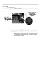
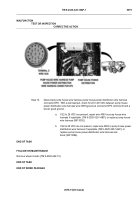
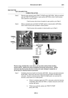
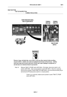
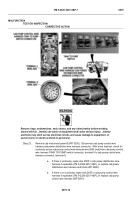
Release pump operator’s panel TANK TO PUMP switch (WP 0004). While an assistant
puts cab TANK TO PUMP switch to closed position (WP 0004), check if tank-to-pump
valve operates to closed position.
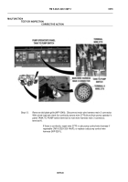
If tank-to-pump valve does not operate to closed position, go to Step 15.
MALFUNCTION
TEST OR INSPECTION
CORRECTIVE ACTION
Back to Top

