TM-9-2320-328-13-P-2 - Page 744 of 1390
TM 9-2320-328-13&P-2
0216-2
DRAFT
0216
-
-
-
-
-
-
-
-
-
-
-
-
-
-
-
-
-
-
-
-
-
-
-
-
-
-
-
-
-
-
-
-
-
-
-
-
-
-
3.
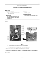
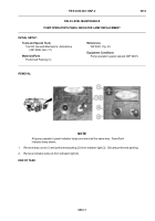
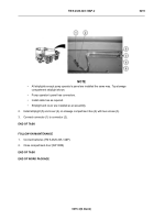
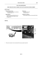
Remove two screws (8), lockwashers (9), and mounting bezel (6) from pressure governor control (3).
Discard
lockwashers.
END OF TASK
INSTALLATION
1.
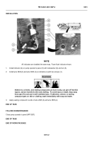
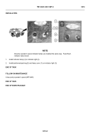
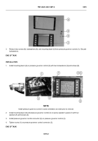
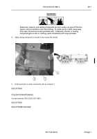
Install mounting bezel (6) on pressure governor control (3) with two lockwashers (9) and screws (8).
-
-
-
-
-
-
-
-
-
-
-
-
-
-
-
-
-
-
-
-
-
-
-
-
-
-
-
-
-
-
-
-
-
-
-
-
-
.
NOTE
Install pressure governor control in same orientation as noted prior to removal.
2.
Install mounting bezel (6) and pressure governor control (3) on pump operator’s panel (7) with four
washers (5) and screws (4).
3.
Install pressure governor control connector (2) on pressure governor control (3).
4.
Tighten screw (1) on pressure governor control connector (2).
END OF TASK
HWT1238
HWT1237
Back to Top


