TM-9-2320-328-13-P-2 - Page 735 of 1390
TM 9-2320-328-13&P-2
0213-1
DRAFT
0213
FIELD LEVEL MAINTENANCE
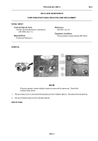
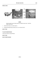
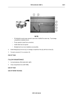
PUMP OPERATOR'S PANEL INDICATOR REPLACEMENT
INITIAL SETUP:
REMOVAL
-
-
-
-
-
-
-
-
-
-
-
-
-
-
-
-
-
-
-
-
-
-
-
-
-
-
-
-
-
-
-
-
-
-
-
-
-
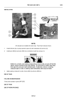
NOTE
•
Tag and mark wires prior to removal to ensure proper installation.
•
All indicators are removed the same way.
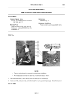
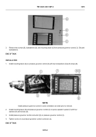
Foam flush indicator shown.
1.
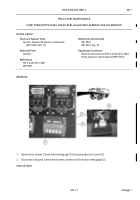
Remove two screws (1), wire 3895 (2), and wire 2849 (3) from indicator (4).
2.
Remove nut (5), lockwasher (6), and indicator (4) from pump operator’s panel (7).
Discard lockwasher.
END OF TASK
-
-
-
-
-
-
-
-
-
-
-
-
-
-
-
-
-
-
-
-
-
-
-
-
-
-
-
-
-
-
-
-
-
-
-
-
-
HWT0264
Tools and Special Tools
Tool Kit, General Mechanic’s: Automotive
(WP 0398, Item 17)
Materials/Parts
Tags, Identification (WP 0400, Item 23)
Compound, Sealing (WP 0400, Item 10)
Lockwasher (1)
References
WP 0391, Fig. 34
Equipment Conditions
Pump operator’s panel opened (WP 0207)
Back to Top

