TM-9-2320-328-13-P-2 - Page 79 of 1390
TM 9-2320-328-13&P-2
0116-19
DRAFT
0116
Change 1
.
.
.
.
.
.
.
.
.
.
.
.
.
.
.
.
.
.
.
.
.
.
.
.
.
.
.
.
.
.
.
.
.
.
.
.
HWT3184
.
WARNING
.
ICON 3
.
Remove rings, wristwatches, neck chains, and any other jewelry before working
around vehicle.
Jewelry can catch on equipment and cause serious injury.
Jewelry
and tools may short across electrical circuits and cause damage to equipment, or
severe burns or electrical shock to personnel.
.
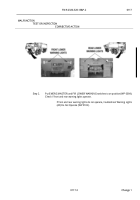
Step 35.
Pull battery disconnect switch to off position (WP 0007).
Remove six screws holding
sunscreen, and place instrument panel in service position (TM 9-2320-325-14&P).
Remove flasher relay (TM 9-2320-325-14&P).
Install test lead set between cab wire
harness flasher relay connector terminals wire 1080 and turn signal “Flasher” yellow
wire.
Disconnect main wire harness from right side clearance/turn light connector
(WP 0228).
Push battery disconnect switch to on position (WP 0007).
Turn Service
Drive Lights On (TM 9-2320-422-10).
Turn right turn signal on (TM 9-2320-422-10).
With a test lead set, check for 22 to 28 VDC between main wire harness wire 1412
(green) at right side clearance/turn light connector, terminal 3 and a known good
ground.
.
If 22 to 28 VDC are present, replace right side clearance/turn
light (WP 0228).
.
MALFUNCTION
TEST OR INSPECTION
CORRECTIVE ACTION
Back to Top


