TM-9-2330-202-13-P - Page 273 of 552
CLEANING AND INSPECTION - Continued
WARNING
DO NOT use a brake drum that exceeds maximum wear specifications. Failure to comply
may result in death or injury to personnel. Seek medical attention in the event of an injury.
6.
Measure inside diameter of brake drum. Discard and replace brake drum if inside diameter exceeds
12.065 in (30.65 cm).
7.
Inspect braking surface of brake drum for cracks, hot spots, and scoring. Discard and replace brake drum
if damaged.
8.
Inspect braking surface for out-of-round at 45 degree intervals. Out-of-round should not exceed
0.015 in (0.38 mm). If runout exceeds 0.015 in (0.38 mm), replace brake drum.
9.
Inspect all remaining components for damage. Replace if damaged.
END OF TASK
ASSEMBLY
1.
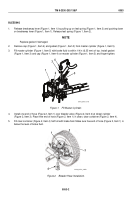
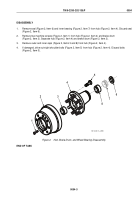
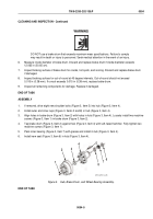
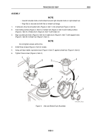
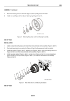
If removed, drive eight new shoulder bolts (Figure 3, Item 5) into hub (Figure 3, Item 4).
2.
Install outer and inner cups (Figure 3, Items 3 and 8) in hub (Figure 3, Item 4).
3.
Align holes in brake drum (Figure 3, Item 2) with holes in hub (Figure 3, Item 4). Loosely install two machine
screws (Figure 3, Item 1) in brake drum (Figure 3, Item 2).
4.
Tap brake drum (Figure 3, Item 2) against hub (Figure 3, Item 4) with soft-faced hammer. Fully tighten two
machine screws (Figure 3, Item 1).
5.
Pack inner bearing (Figure 3, Item 7) with grease and install in hub (Figure 3, Item 4).
6.
Install new seal (Figure 3, Item 6) in hub (Figure 3, Item 4).
1
2
3
4
5
6
7
8
M116_M101_4-86
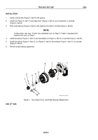
Figure 3.
Hub, Brake Drum, and Wheel Bearing Assembly.
END OF TASK
TM 9-2330-202-13&P
0054
0054-5
Back to Top

