TM-9-2330-202-13-P - Page 275 of 552
WHEEL BEARING ADJUSTMENT
NOTE
•
If performing wheel bearing adjustment as part of troubleshooting when wheel assembly
has not been removed, perform Steps 1 through 12.
•
If performing wheel bearing adjustment as a follow-on to hub, brake drum, and wheel
bearings maintenance, perform Steps 5 through 12 only.
1.
Apply handbrakes. Chock wheel assembly opposite the side being adjusted. Raise vehicle at front and rear
corners of side being maintained until wheel assembly is clear of ground. Support vehicle with suitable
support stand.
2.
Release handbrake on side being adjusted (WP
0005).
3.
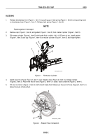
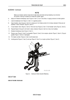
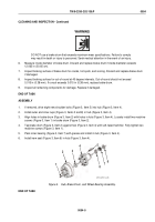
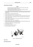
Remove grease cap (Figure 5, Item 1) from hub (Figure 5, Item 4).
4.
Remove cotter pin (Figure 5, Item 2) from spindle (Figure 5, Item 5). Discard cotter pin (Figure 5, Item 2).
5.
Loosen nut (Figure 5, Item 3) on spindle (Figure 5, Item 5) until hub (Figure 5, Item 4) and brake drum
(Figure 5, Item 6) turn freely.
6.
Torque nut (Figure 5, Item 3) to 30 lb-ft (41 N•m) while turning hub (Figure 5, Item 4) and brake drum
(Figure 5, Item 6), to seat bearings.
7.
Back off nut (Figure 5, Item 3) 1/16 turn. Finger-tighten nut.
8.
Install new cotter pin (Figure 5, Item 2) in spindle (Figure 5, Item 5) and bend back ends. Make sure hub
(Figure 5, Item 4) and brake drum (Figure 5, Item 6) turn freely.
9.
Install grease cap (Figure 5, Item 1) on hub (Figure 5, Item 4).
10.
Apply handbrakes (WP
0005).
11.
If removed, install wheel assembly (WP
0055).
12.
Remove lifting devices and lower vehicle.
1
2
3
4
5
6
M116_M101_4-89
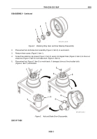
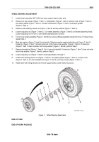
Figure 5.
Wheel Bearing Adjustment.
END OF TASK
END OF WORK PACKAGE
TM 9-2330-202-13&P
0054
0054-7/8 blank
Back to Top

