TM-9-2330-202-13-P - Page 281 of 552
ASSEMBLY
NOTE
•
Use left shoulder bolts on left wheel hub and right shoulder bolts on right wheel hub.
•
Align flat on shoulder bolt with flat on wheel hub flange.
1.
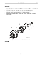
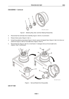
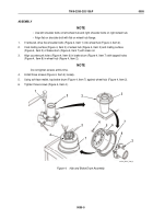
If removed, drive five shoulder bolts (Figure 4, Item 1) into wheel hub (Figure 4, Item 2).
2.
Coat mating surface (Figure 4, Item 3) of wheel hub (Figure 4, Item 2) and mating surface
(Figure 4, Item 5) of brake drum (Figure 4, Item 7) with clean oil.
3.
Align countersunk holes (Figure 4, Item 6) in brake drum (Figure 4, Item 7) with tapped holes
(Figure 4, Item 8) in wheel hub (Figure 4, Item 2).
NOTE
Do not tighten screws at this time.
4.
Install three screws (Figure 4, Item 4) loosely.
5.
Using soft-face mallet, tap brake drum (Figure 4, Item 7) against wheel hub (Figure 4, Item 2).
6.
Tighten three screws (Figure 4, Item 4).
1
2
2
3
4
5
6
7
8
2
2
7
4
M116_M101_4-90_3
Figure 4.
Hub and Brake Drum Assembly.
TM 9-2330-202-13&P
0055
0055-5
Back to Top

